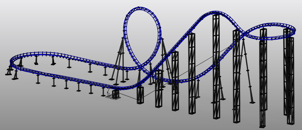
Inspired by the design and construction of early modern steel roller coasters, this personal project explores the complete development of a functional scale roller coaster. From initial concept and CAD modeling to manufacturing, assembly, and testing.
The coaster layout was initially modeled using NoLimits 2 Roller Coaster Simulation, where the track geometry and center spine were developed. The spine was then imported into SOLIDWORKS and served as the primary reference for designing the track, supports, and mechanical components. The final design has a maximum height of 4.5 ft and a footprint of 14.5 ft × 3.25 ft, incorporating additive manufacturing, mechanical fastening, and a powered chain lift system into a physical prototype.
The Design
The design process for this roller coaster was quite a challenge. Although the initial layout was created in NoLimits 2, there was still a significant amount of work required before it could become a physical model. NoLimits 2 allowed me to export a .csv file containing spline points for the coaster’s centerline, which then served as the foundation for developing the track geometry in SOLIDWORKS.
Because only the center spline was exported, the actual track structure had to be built around that path, requiring careful attention to rail placement, spacing, and overall geometry. At the same time, I had several real-world design constraints to consider. I knew early on that the project could quickly become too large and difficult to manage, so establishing a practical scale and overall footprint became one of my first priorities.
I drew much of my inspiration from early Arrow Dynamics. These rides helped shape the early development of the modern roller coaster, and their track and train designs remain incredibly distinctive and recognizable.
One of my biggest influences was The Demon at Six Flags Great America, originally known as Turn of the Century. The Demon has always held a special place for me because it was the first roller coaster I rode that featured inversions. With its back-to-back vertical loops and double corkscrew, it became one of the rides that first sparked my fascination with roller coasters and ultimately influenced the direction of this project.
I decided to use a 1:12 scale, where one foot in NoLimits 2 represented one inch on the physical model. From there, I had to balance the overall footprint with another important consideration: keeping the coaster large enough to incorporate commercially available components. With both constraints in mind, the final design still resulted in a sizable footprint, but the added space ultimately made the project more practical to build and assemble.
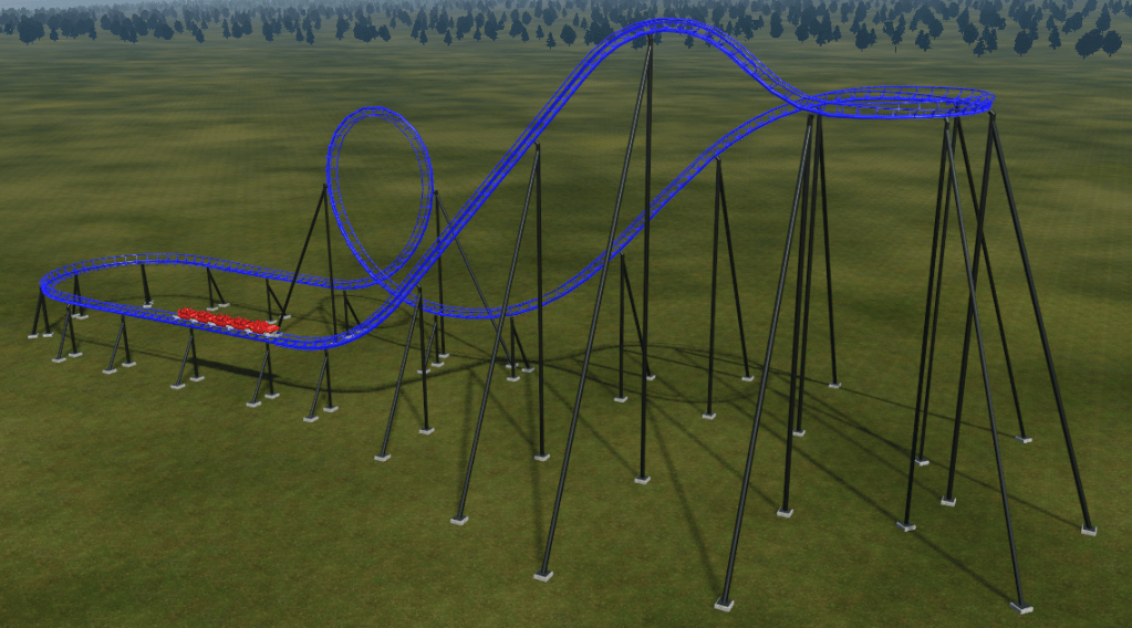
Another major factor in the design was the track geometry. With the overall footprint already established, I wanted to keep the layout relatively simple to make both the design and fabrication process more manageable. Since I knew the track would be produced using Fused Filament Fabrication (FFF), overly complex geometry could have created significant challenges during printing and post-processing.
By keeping the track geometry relatively straightforward, I was able to simplify fabrication and greatly reduce the amount of post-processing required. I’ll discuss the fabrication process in more detail later on this page.
Fabrication
For the fabrication of this project, I relied on several pieces of software and one major piece of hardware. As mentioned earlier, NoLimits 2 was used to develop the initial coaster layout, while most of the detailed design work took place in SOLIDWORKS, where the concept was transformed into a manufacturable model.
Once the design was ready, I used my Bambu Lab P1S 3D printer to bring the coaster from CAD into the physical world. The printer quickly became one of the most important tools in the project, running for long periods of time throughout both the day and night. Considering the amount of printing involved, the process was remarkably reliable. I encountered a few failed “spaghetti” prints along the way, but most issues were identified early, corrected, and prevented from becoming recurring problems. Overall, the printing process went smoothly and allowed the project to move steadily from digital design to physical assembly.
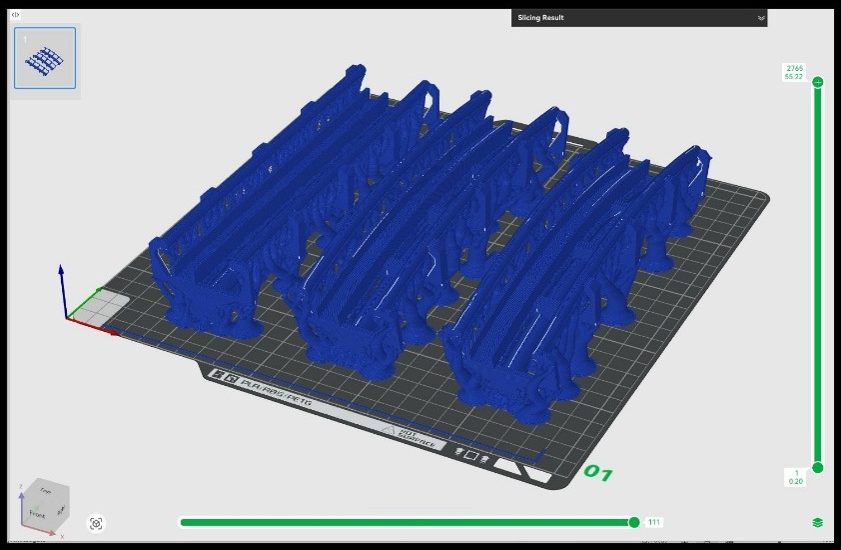
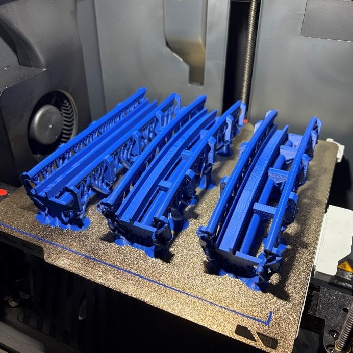
Bringing the design to life was one of the most rewarding parts of this project. Creating something in CAD is one thing, but seeing those designs take shape as physical components adds an entirely different level of satisfaction to the process. The photos below highlight a few examples of how the digital models progressed from SOLIDWORKS into finished, tangible parts.
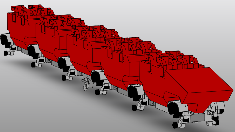
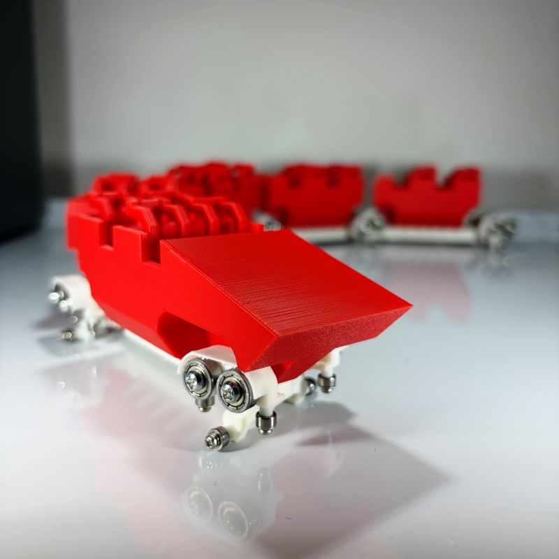
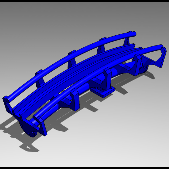
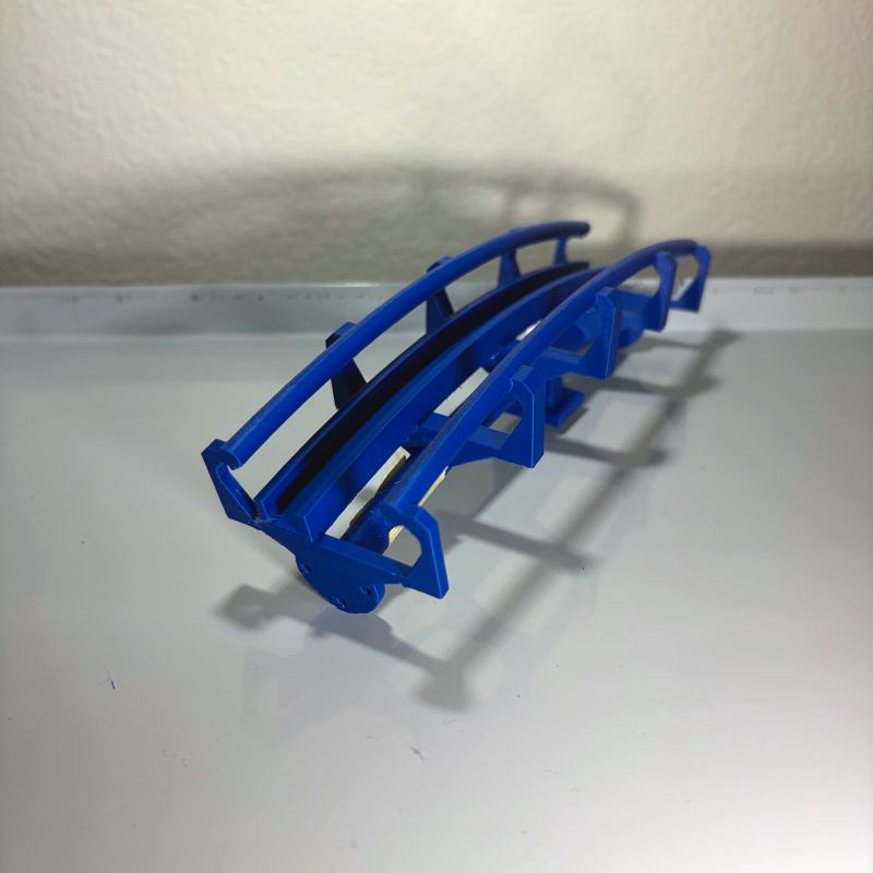
Assembly was achieved through a combination of specified tolerances for snap-fit components and mechanical fasteners of various sizes.
These components demonstrate both methods. In the upper photo, a fully printed track section is secured to the support using M2 machine screws and hex nuts. The mounting plate also utilizes a tight-tolerance fit with the support structure.
The bottom photos show the motor-driven system and its connection to the coaster structure. The motor is secured to the base plate using threaded heat-set inserts, while a U-clamp fastens the motor assembly to the support column.
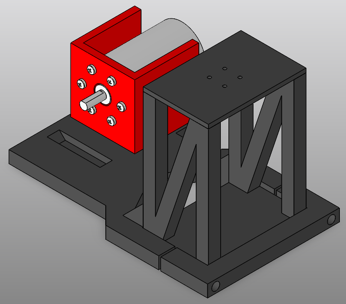
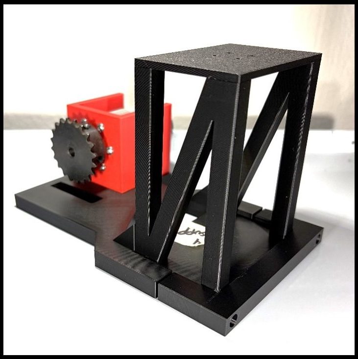
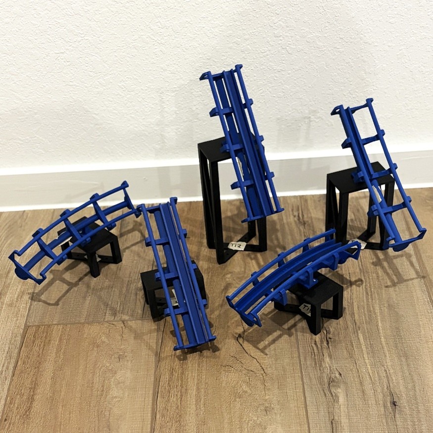
As of now, this project is in its final stages. The track sections have been connected to their respective supports, the train has been assembled, and all remaining components have been printed and post-processed.
With the start of my senior-year fall semester at the University of Houston, progress has slowed as coursework has taken priority. Even so, I am looking forward to completing the final assembly and capturing a working video of the coaster in operation.
This page will continue to be updated as the project progresses.
Engineering Drawings
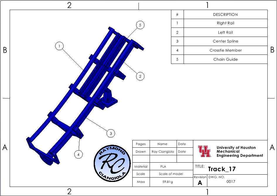
The drawing above is not intended to serve as a technical drawing, but rather as a visual breakdown of a single track section. It highlights the basic construction, geometry, and individual features that make up each piece. In total, the roller coaster is made up of 63 individual track sections.
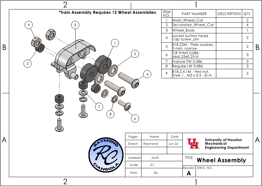
The assembly drawing above provides a detailed exploded view of a single wheel assembly. It serves as an important reference during the build process by clearly showing how each component fits together to ensure the assembly functions as intended. The drawing also includes a Bill of Materials (BOM) identifying the required components. Each train uses a total of 12 wheel assemblies.

